
Download sources for this chapter
Edit: The beginning of chapter 03 was written in past tense, because the corresponding notes were just summarizing how I found an assembler. There were lots of back and forth most of which I deemed too useless to take notes about.
Introduction
I had no idea that finding a decent 68k assembler for windows would have been that difficult (at least if you are not a cygwin fan). I encountered so many dead-ends that I seriously considered making my own.
Among the assemblers I found, the most promising was “vasm”, a multi-cpu, multi-syntax, multi-host, multi-output assembler that clearly stated it supported m68k and motorola S-REC files. The only problem being that despite its multi-host capabilities, it didn’t support windows.
As a last resort before writing my own assembler, I decided to try and compile it myself. After all it was written in C, so there was a chance it would compile on windows.
Migrating to vasm
So, I used mingw/msys and tried to compile with the following options:
make CPU=m68k SYNTAX=mot
This failed because msys has no ‘CC’ variable defined, so I corrected this as follows:
make CPU=m68k SYNTAX=mot CC=gcc
Which worked like a charm.
I now had a standalone assembler executable. But that didn’t assemble my test files. Maybe the “mot” (motorola) syntax was not the correct one. I’ve tried them all and finally the “oldstyle” seemed to somehow work:
make CPU=m68k SYNTAX=oldstyle CC=gcc
That is, excluding the ‘*’ comments which it didn’t recognize and the END directive that worked somehow differently (the END START line produced an error that said the “START” was garbage, so I removed it and it worked).
Now the only thing left was to make the assembler produce an S-REC file, instead of the “a.out” weird listing it produced by default. Here are the command line options to do that:
vasmm68k_oldstyle.exe -Fsrec -s19 -o test.s68 test.x68
I compiled my previous blue-screen test, and a red-screen variant just for fun and they seem to work fine.
Now I’d like to find out how can we include files using this assembler. Taking a look at the docs.
It simply is:
include file
Let’s try that. I’m going to make a separate assembly file that sets the background to green this time and include it right after setting to blue:
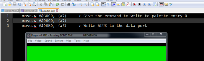
I needed to indent the “include” directive, otherwise it produced an error, and the filename must have been in quotes, but otherwise, it worked.
Also I found out something useful: if you just write to VDP’s data port a second color, it’s not going to replace the first one, but it will increment the target color by 1 (2 bytes) so you can write multiple entries in the palette with one command to the control port and multiple writes to the data port. Useful.
Automatic build
Now, to somehow automate the building process. We now have a command line assembler, but it doesn’t help if we invoke it by hand. To summarize, the current situation looks like this:
- We have a .x68 file, containing our assembly code, plus as many include files as we want, in the same directory.
- The assembler searches for include files in the current directory, so we must run it from there.
- The assembler produces a .s68 S-REC file with our program, in machine code
- Our “romtool” reads the .s68, plus a “header” binary located in its own directory (so it must be run from there) and produces the final ROM binary.
- Regen (emulator) can load games from the command line!
The only problematic thing here is the “header” binary the romtool reads, which prevents it from working in any path other than its own. Maybe its time to ditch the external dependency. After all, it’s just 512 bytes, so why not embed them directly in the source?
I swear I’ve made this bin2c program a thousand times, but it’s nowhere to be found. I’m just going to modify the existing romtool to spit out the bytes in hex…
Done. We got rid of the dependency and romtool can now be called from anywhere. Now let’s create a bat file to automate the process…
I made a quick bat for now, that just calls the 3 programs (assembler, romtool, emulator) one after another. Maybe I’ll somehow make it stop if anything fails in this sequence, but for now, I’m just happy to be able to test my code instantly.
..\..\tools\vasm\vasmm68k_oldstyle.exe -Fsrec -s19 -o test.s68 test.x68
..\..\tools\romtool\romtool.exe test.s68 test.bin
..\..\tools\regen\regen.exe %~dp0test.bin
I promised this chapter would have been boring, didn’t I?
Now what?
I’m a bit unsure about how to proceed.
Now that we have an acceptable development system, the next t hing I was planning to do was to fully initialize the VDP. I’m pretty sure this is going to involve a ton of repeating code, for initializing the various registers and memory locations of the VDP, using the same two (data + control) ports.
So we could surely use some structure in our code. Maybe create some subroutines to perform frequent tasks and see if the assembler provides macros. That could help too.
Subroutines
Back to the 68K tutorial:
http://mrjester.hapisan.com/04_MC68/Sect05Part04/Index.html
http://mrjester.hapisan.com/04_MC68/Sect05Part05/Index.html
So CALL and RET in 68k are JSR (jump to subroutine) and RTS (return from subroutine). Before we can use them, we must initialize the stack first.
My decision to allocate a7 for the VDP was unfortunate, as the 68K treats it as the stack pointer. Identifiers ‘sp’ and ‘a7’ refer to the exact same register, so we’ll need to put the VDP’s port elsewhere, maybe a5. But first we need to decide where to put the stack. Let’s review the memory map in sega2 document again…
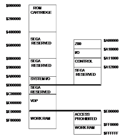
Am I stupid for not understanding this? The text above the image says this image displays the difference between the two modes: 16-bit mode and master system compatibility mode. I’m going to guess that the right hand side is for the 16-bit mode because it has a mapped area for the z80. So our work RAM must be in the range FF0000-FFFFFF, which gives us 64K to play with.
So let’s put our stack pointer to FFFFFF:
move.l #$FFFFFF, sp
And let’s create a separate assembly file for system initialization. I’ll approach this by creating a subroutine there that will perform the initialization, then include the file at the bottom of our program and call the subroutine from our main program, so that the interesting stuff remains on top of the binary.
Silly me, you cannot initialize the stack pointer in a subroutine! This must be the first thing we must do in our program. Let’s just do that.
And… all hell broke loose.
Remember what we said about odd addressing? FFFFFF is odd, isn’t it? So maybe, just maybe we shouldn’t have put the stack pointer there! I put it at $1000000 and the subroutine works just fine. a7 is decremented by 4 bytes first and then the return address is copied on top of stack:
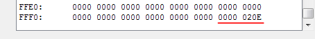
This is also the last memory location that regen allows me to see, which means our assumption was correct: Mega Drive’s working memory is from FF0000 to FFFFFF. The emulator shows only the last 4 hex digits of the address though. Strange, but then again those are the important ones.
Macros
Because I’m extremely lazy, I checked the vasm documentation hoping to find some macro mechanism that will facilitate certain tasks (like packing a word to set a VDP register).
I wrote the following as a joke, but I’m truly amazed the assembler could actually parse it:
    macro VDPSetRegister, register, value
        move.w #((( $80 | \register) << 8 ) | \value), (a5)
    endmacro
So now, we can easily set a VDP register by writing the following, and all the packing required happens during assembly time:
VDPSetRegister registerIndex, value
Now, since we have the luxury of macros, we needn’t allocate our precious address registers to point to the VDP ports. We can simply hard-code the port addresses in the macro:
    macro VDPSetRegister, register, value
        move.w #((( $80 | \register) << 8 ) | \value), $C00004
    endmacro
Not sure which method is optimal. I guess using an address register will generate a more compact instruction, but I wont let myself worry about that.
Even better, we can use a nested macro for writing a register:
    macro VDPWriteToControl, value
        move.w \value, $C00004
    endmacro

    macro VDPSetRegister, register, value
        VDPWriteToControl #((( $80 | \register) << 8 ) | \value)
    endmacro
A little voice in my head says this is not at all how they programmed the console back in the 90s, and it goes on to say that if that’s the way it’s gonna be, I’d be better off using a C compiler or something.
I’m ignoring the voice.
After adding one more macro to write to the data port, here is how our previous “blue screen” test looks like:
    VDPWriteToControl #$C000    ; Give the command to write to palette entry 0
    VDPWriteToControl #$0000
    VDPWriteToData #$0E00        ; Write BLUE to the data port

    VDPSetRegister 7, 0         ; Set VDP register #07 (BGColor) to 0

    VDPSetRegister 0, $04        ; Set r#00 as the manual says
    VDPSetRegister 1, $44        ; Set bit 7 of VDP r#01, to enable display
Initializing the VDP
After spending about half an hour making sure there’s absolutely nothing left to do to make my life easier, it’s time to do this full VDP initialization we talked about in Chapter 2.

OR, I can take a break and go for a walk! After all, it’s better to do this kind of thing with a clear head, isn’t it?
Ok, I’m back! I’m so bored to do the following that I took one of my long walks today.
The “long walk” protocol is simple: I choose a random direction and walk as far away from home as possible, taking random turns as I go, until I get lost. Then I use my (often perfect) sense of direction to guide me home.
This randomness makes the walk a bit more adventurous. You never know what lies after the next corner (mostly houses though). It also is an interesting way to burn some calories… At least more interesting than the treadmill.
Let us first set all the VDP’s registers, since we already have the relevant macros. I’m going to do this by looking at the docs, see what a specific register does, and then de-activate all features that I don’t understand or that I’m not going to use.
Here is a first draft:
systemInitVDP:
    VDPSetRegister  0, $04        ; R#00 : HInterrupt=0
    VDPSetRegister  1, $4C        ; R#01 : Display=1, VInterrupt=0, DMA=0, Vertical 30 Cell mode (PAL)
    VDPSetRegister  2, $00        ; R#02 : Pattern name for SCROLL A
    VDPSetRegister  3, $00        ; R#03 : Pattern name for WINDOW
    VDPSetRegister  4, $00        ; R#04 : Pattern name for SCROLL B
    VDPSetRegister  5, $00        ; R#05 : Sprite Attribute Table
    VDPSetRegister  6, $00        ; R#06 : Should be zero
    VDPSetRegister  7, $00        ; R#07 : Background Color: 00PP CCCC
    VDPSetRegister  8, $00        ; R#08 : Should be zero
    VDPSetRegister  9, $00        ; R#09 : Should be zero
    VDPSetRegister 10, $01        ; R#10 : HInterrupt timing - probably '1' means "every scanline"
    VDPSetRegister 11, $00        ; R#11 : ExternalInterrupt=0, Vscroll=Hscroll="full"
    VDPSetRegister 12, $81        ; R#12 : Horizontal 40 cell mode, no interlace, no shadow/highlight
    VDPSetRegister 13, $00        ; R#13 : HScroll data table
    VDPSetRegister 14, $00        ; R#14 : Should be zero
    VDPSetRegister 15, $02        ; R#15 : Auto-increment by 2 bytes each RAM access
    VDPSetRegister 16, $00        ; R#16 : Scroll size: H32, V32 cell
    VDPSetRegister 17, $00        ; R#17 : WINDOW 0 cells from left
    VDPSetRegister 18, $00        ; R#18 : WINDOW 0 cells from bottom
    VDPSetRegister 19, $00        ; R#19 : DMA Length counter low
    VDPSetRegister 20, $00        ; R#20 : DMA Length counter high
    VDPSetRegister 21, $00        ; R#21 : DMA Source Address Low
    VDPSetRegister 22, $00        ; R#22 : DMA Source Address Medium
    VDPSetRegister 23, $00        ; R#23 : DMA Source Address High
    rts
DMA
Then, it would make sense to zero the VDP’s memory. What would be the best way to do this? We can access VRAM through the VDP ports, or we can use a “DMA Fill”, which sounds better. Here is the procedure to perform a DMA Fill:
We first need to turn on the DMA bit (M1) of register #1. After the DMA operation is complete, it will be reset to 0 automatically. Let’s first make a few more macros to read back VDP registers and automate toggling specific bits.
Nope, the registers are write-only, except from the “status” register which is read-only. For now, we’re just going to refill r#01:
VDPSetRegister 1, $5C
Next, we need to specify the fill length in registers 19 and 20. The VDP has 64K of VRAM, so I’m a bit unsure of what to put in there. I can’t fit a value greater than FFFF, so maybe a value of 0 will fill the entire thing.
This will be my second experiment, but for now, let’s just fill FFFE bytes:
    VDPSetRegister 20, $FF
    VDPSetRegister 19, $FE
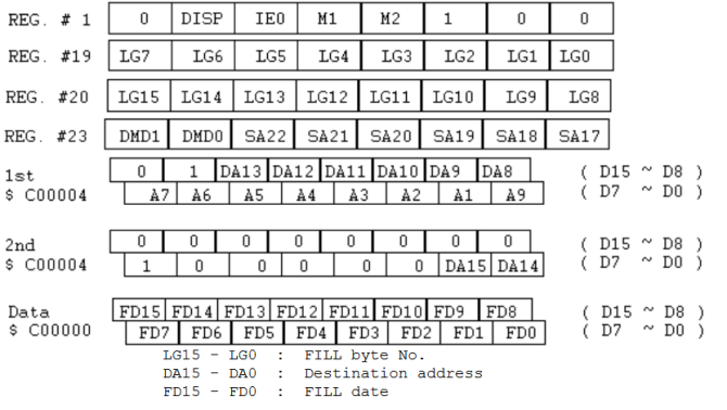
Then, we need to fill register #23 with the pattern MMSS SSSS. First two bits is “DMA mode”, which in our case is ’10’ (VRAM fill) and rest of the bits are for source address (in case of DMA copy), which we’ll set to zero:
VDPSetRegister 23, $80
Next, we have two writes to the control port, containing the destination address, scattered. Fortunately, our destination is zero, so:
    VDPWriteToControl #$4000
    VDPWriteToControl #$0080
Finally (omg!) we must write the fill pattern to the data port (let’s try ABCD as a test fill):
VDPWriteToData #$ABCD
Note that this ain’t the whole story. Register #15 contains the “increment” value. We set that to ‘2’ previously while initializing, so this is going to be a 16 bit fill. Let’s leave it at that and do the test…
Hehehehe ….
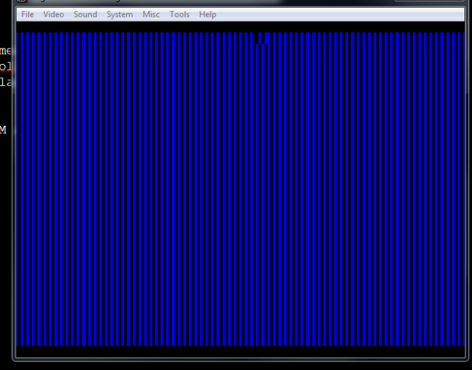
Something was accomplished here. Probably not what we wanted though. The blue stripes are of color 0, so we might have filled zeroes every other byte or so. Let’s take a look at the contents of VRAM:
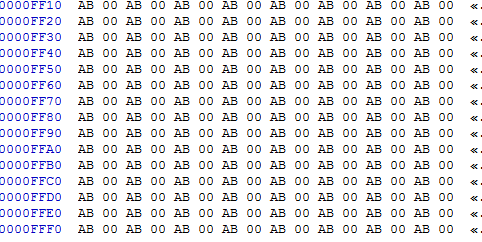
It’s filled allright, but only with “AB”. What happened to “CD”? Also, why is it filled all the way to the end (FFFF)? Maybe the fill length is in “increments” and not in bytes. Let’s try to fill fewer bytes, say the first 256:
    VDPSetRegister 20, $01
    VDPSetRegister 19, $00
Fuck…
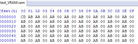
Now we know the length is in ‘increments’. It fills about 512 bytes. 514 to be exact, and only the first two bytes contain my data. Inverted.
…
Ok. The inversion is normal. The filler starts with the lower byte. Also the “increments+1” is normal-ish. That is if you interpret the “DMA starts at after (E)” to mean that. I’m buying it and say I want to fill 255 bytes instead.
Also, for my psychological well-being, I’m going to assume that the zeroes are just a silent emulator bug. Maybe there aren’t any games that try to fill VRAM with words (you normally fill with zeroes anyway). I’ll set the auto-increment (register 15) to be 1 by default and both high and low bytes to be the same ‘AA” and it better work.
Respect my authorita:
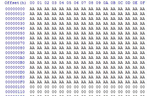
Ok. Now we have some sense of control over the VRAM fill thingy. Also, this “increments + 1” allows us to fill the entire VRAM. Let’s now fill it with zeroes and forget about it.
Not so fast! Literally. Before we’re through with this, we must first wait for the operation to finish. I don’t feel that comfortable issuing more commands to the VDP while it’s filling its memory.
To do that, we must first read the VDP “status” register.
To do this, we just read the “control port” address (C00004). Bit 3 is the DMA bit. DMA is active while this bit is ‘1’.
Let’s first create a macro to read the register:
    macro VDPReadStatus, value
        move.w $C00004, \value
    endmacro
The macro takes a register as its argument, and copies the status byte to that register.
Now, how do we loop with a specific bit as a break condition? The 68K has a handy BTST instruction that checks bits, and another one that branches based on the zero flag:
systemInitVDP_loop0:
    VDPReadStatus d0
    btst #3, d0
    bne systemInitVDP_loop0        ; wait until bit 3 (DMA) of status register is cleared
Here is how the condition works:
- btst will test bit #3 (DMA)
- If bit 3 is set, the zero flag will be zero
- This means “not equal” (because when doing comparisons, you subtract, and if the result is zero, this sets the zero flag, which in turn means equal)
- We branch back on “not equal” with bne
I would really prefer the instruction to be jnz. This extra step of “equality” took the best of me.
Since we may do some more DMA in the future, let’s make a subroutine to wait for DMA:
VDPWaitForDMA:
    VDPReadStatus d0
    btst #3, d0
    bne VDPWaitForDMA
    rts
I put that in a separate file called “VDP.x68”, which will be the place to put all VDP related routines.
Afterword
In this chapter we achieved significant progress. We learned about subroutines and macros, we performed a DMA operation and we more or less put the VDP in a defined state.
That’s not the kind of progress that I like. I very much prefer the visual stimulation of new stuff appearing on the screen, but nevertheless we covered a lot of ground towards that.
Next time, I want a sprite on the screen!
| Previous Chapter | TOC | Next Chapter |
